

The initial radiographic exam should assess its diagnostic capacity. After this, the clinician may interpret the image to reach a diagnosis. The clinician should also recognise any image faults or artefacts which may reduce the radiograph's accuracy, and take steps to prevent them.
Radiographic report
The clinician fills out the radiographic report upon viewing the image, which provides a structured record of the image's interpretation, determining whether it is diagnostic or not, and then detailing abnormalities and possible diagnoses. A template radiographic report (word file) has been uploaded at the bottom of this section which can be used by the clinician. It comprises four main sections in order as follows.
Description. Basic patient information (name, signalment and history) and imaging details (area imaged, views/projections used) are included. For example, "Abdominal x-ray with dorsoventral and left lateral projections". It then notes the quality of the radiograph (exposure, positioning, faults and artefacts), commenting on whether it is diagnostic or not.
Radiographic Diagnosis. This section details all visible structures (stomach, kidneys etc), then highlights abnormal findings and provides an interpretation based on roentgen signs. It then ends with a summary.
Differential Diagnosis. A prioritised list of differential diagnoses is generated from the radiographic diagnosis, with the most significant differentials listed first and incidental findings last.
Recommendation. The clinician describes the next steps for the case, either additional testing if the diagnosis is unclear, or treatment if it is clear.
Choose radiographic projections
Projections are named based on the direction of the x-ray beam, e.g. dorsoventral (enters dorsally, exits ventrally). Two projections (orthogonal views) are needed for a 3D view of the patient. Standard views, positioning and exposure settings are used to minimise variation between images. An abdominal X-ray series typically includes ventrodorsal, right lateral and left lateral views. The clinician may opt for one lateral view in some cases (respiratory compromise). The widget below shows directional anatomy, and how we can combine entry and exit points to give numerous views (dorsoplantar, craniocaudal). Try labelling the simplified and advanced images!
Click on the bullets or arrows below to navigate between slides.
Ensure correct orientation
Clinicians use standardised orientations when reviewing radiographs to minimise variation and ensure consistency in diagnoses. Digital radiography allows image manipulation like mirroring and adding a left/right marker to achieve desired results. These include:
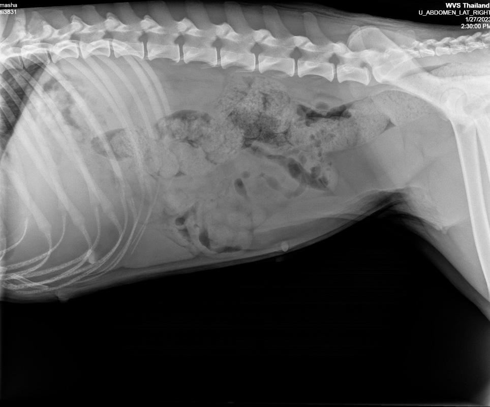
Head to the left. In lateral images, the patient's head is always on the left of the image, regardless of left or right lateral views. If the digital radiograph shows the head on the right, the clinician may flip it using the editing controls to move the head to the left.
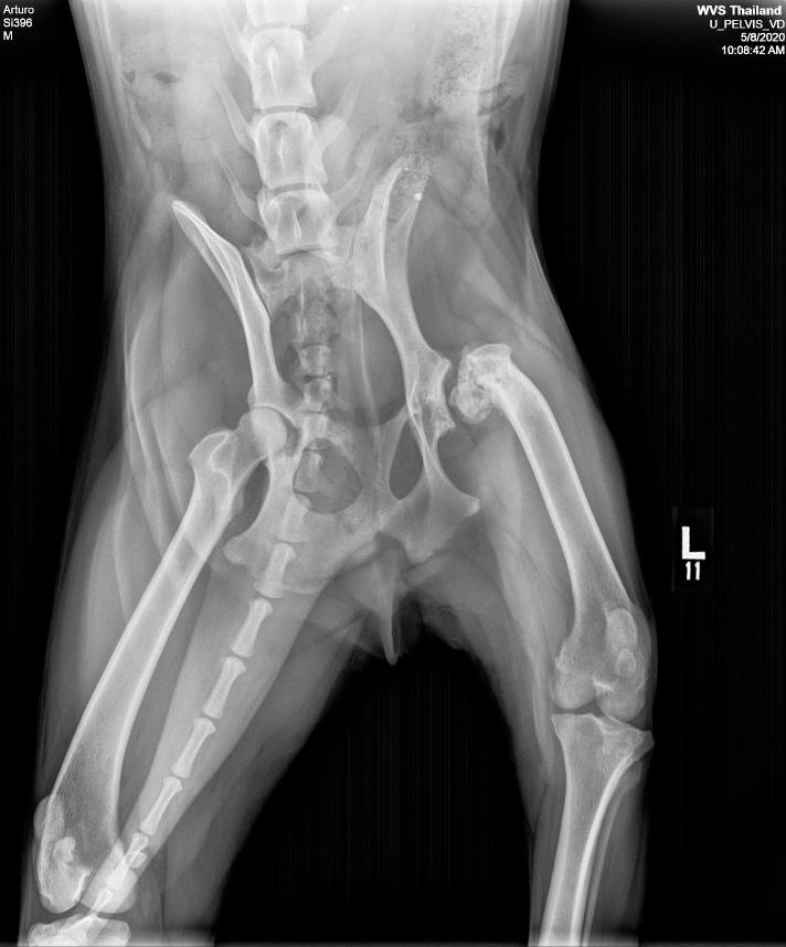
Matched left/right marker. In dorsoventral and ventrodorsal views, the marker should match the same leg as the patient. In lateral views, the marker should match the view, i.e. right marker for right lateral (patient's right side to the plate). The following image is a ventrodorsal projection (dog's back on plate, legs in the air), so the marker is oriented to match the same leg (left).
Evaluate image exposure
After orienting the image, assess whether it is over-exposed (too dark), under-exposed (too light), or correctly exposed. A correct exposure provides good contrast and image quality, allowing evaluation of both soft tissues and bony structures in the same image.
Assess radiographic positioning
To ensure diagnostic accuracy, it is important to evaluate patient positioning and collimation of the radiograph. Incorrect positioning, such as a rotated spine, may cause incorrect overlapping of structures, making it difficult to identify lesions. Incorrect collimation that is too small may lead to missed vital structures, but collimating too large will expose operators to higher levels of scatter radiation. Other positioning faults also cause distortions, reducing its diagnostic accuracy. We need to assess for positioning faults, make adjustments, and retake the x-ray if needed.
Geometric Distortion. If the patient's legs are not parallel to the plate, they may appear artificially shorter or longer on the image. Avoid this by positioning the patient's area of interest perpendicular to the primary beam.
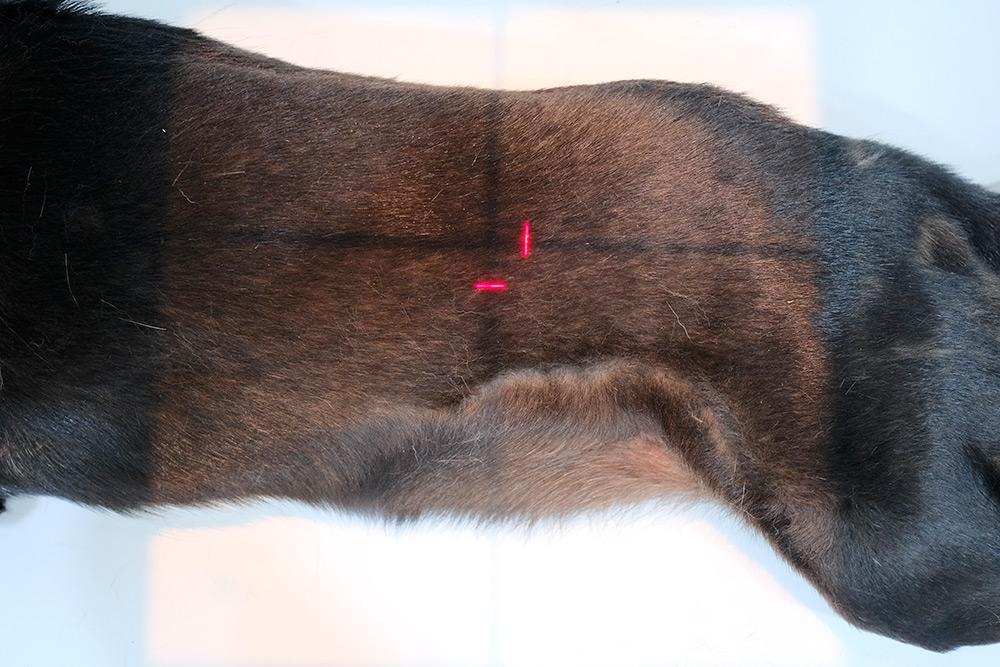
Centring. The area of interest should be in the centre of the beam, with collimation used to include only what is necessary. This helps minimise scatter radiation and reduces the patient's exposure to harmful radiation.
Magnification. The greater the distance between the object of interest and the plate, the more the beam diverges and the bigger the object appears in the image. Prevent this by keeping the object of interest close to the plate. For example, put the patient in left lateral to visualise the heart, as this is closer to the left body wall.
Assess for technical faults
Most common faults noticed by clinicians, and ways to avoid them:
Lack of or incorrectly placed left/right marker. The clinician may add or draw in the left-right marker in post-processing (digital radiographs), however, if they are unsure of orientation, the image may need to be retaken to avoid confusion down the line.
Poor positioning. The patient's limbs may be obstructing other structures or their body may be incorrectly rotated, causing organs to overlap. This will require the radiograph to be taken again after adjusting the patient's position.
Poor collimation. Often clinicians expose an area larger than the area of interest, leading to unnecessary radiation exposure and scatter. If the collimation is too small, vital structures (diaphragm, neck of bladder) may be missed from the field.
Movement blur. Occurs if the exposure time is set too long (on a mobile body part like the lungs), or if a patient moves during the x-ray (lack of restraint). The x-ray will likely need to be taken again, with a shorter exposure time or better patient restraint.
Fogging. Caused by scatter radiation which produces noise, reduces contrast and darkens the image. Using filter grids when the depth is over 10cm will prevent this. These grids reduce scatter radiation, thus minimising fogging.
Double exposure. If an image is not unloaded from an x-ray plate, and another radiograph is taken, two images will appear stacked on top of each other (a double exposure). The digital x-ray plate should be erased, or a new film slide should be loaded and the radiograph may be taken again.
Radiopaque artefacts. Water or dirt on a patient's coat, collars and microchips may be seen as radiopaque structures. Patients should be clean and dry before radiographs are taken, with collars removed when imaging the thorax and neck area. Anaesthetised patients maintained on gas will also have an endotracheal tube visible in their trachea.
Use the roentgen signs
When interpreting a radiograph we describe abnormal findings using the roentgen signs. This is written in the "radiographic diagnosis" section of the report. The roentgen signs are:
Size. This may be increased (hyperplastic, neoplastic, entrapment, hypertrophic) or decreased (hypoplastic, atrophic, or congenitally missing). For example, a report might say "Heart silhouette enlargement present".
Shape. An organ may differ from its normal shape, either localised or diffusely throughout. For example, the kidney may differ from its normal shape as a result of neoplasia, or necrosis.
Number. This may be increased in limb radiographs, for bones with additional ossification centres, or decreased in the case of a congenital anomaly, i.e. a cat with only one kidney.
Position. The normal position of an organ may be displaced, for example intestines may be displaced cranially in the case of a diaphragmatic herniation.
Opacity. This may be increased (i.e. bladder calculi are radiopaque), or decreased (where abnormal gas is present, such as in pneumoperitoneum).
Margination. Differences in opacity allow distinction between neighbouring structures. We can use this to determine changes. For example, bones are more radiopaque than surrounding cartilage, making it easier to differentiate. A change to these margins, making it difficult to distinguish them, suggests a periosteal reaction is occurring. In the abdomen, reduced margination between organs may suggest free fluid.
These abnormalities are identified and summarised, before differentials and further diagnostics or treatment options are defined. We will talk about specific radiographic interpretation in the following sections.